
Please Choose Your Language
- All
- Product Name
- Product Keyword
- Product Model
- Product Summary
- Product Description
- Multi Field Search

Views: 0 Author: Site Editor Publish Time: 2026-08-21 Origin: Site


Precision electronics manufacturing demands exactness at the microscopic level. Component failure often traces back to microscopic inconsistencies in wire insulation, tension spikes during winding, or thermal degradation, rather than macro-level design flaws. Balancing ultra-low resistance, mechanical flexibility, and thermal stability in increasingly miniaturized sub-0.2 mm form factors presents a tough engineering challenge. Standard off-the-shelf wire frequently fails under the stress of high-speed automated winding or the extreme operating temperatures found in modern densely packed circuitry.
Engineers must move beyond basic gauge selection to build a highly reliable end product. This requires a systematic evaluation framework for specifying fine enameled wire. By analyzing conductor metallurgy, insulation chemistry, thermal classes, and manufacturer quality controls, design teams can eliminate variables that lead to premature field failures and costly manufacturing defects.
Thermal Class Dictates Reliability: Selecting the correct insulation chemistry (ranging from 155°C to 240°C) is critical for preventing dielectric breakdown in high-load electrical components.
Conductor Material Trade-offs: While standard enameled copper wire suits most applications, specialized alloys or silver are required for ultra-low resistance in highly constrained form factors.
Dimensional Tolerance is Non-Negotiable: In precision winding, even minor deviations in insulation build or wire diameter cause tension spikes, leading to elongation or breakage during automated manufacturing.
Vendor Capabilities Matter: Partnering with a specialized magnet wire manufacturer ensures batch-to-batch consistency, adherence to NEMA/IEC standards, and access to custom winding wire profiles.
The fundamental challenge in micro-coil design is the inverse relationship between wire diameter and electrical resistance. As the physical space for a coil shrinks, you must specify thinner wire to achieve the required number of turns. Reducing the cross-sectional area of the conductor directly increases its electrical resistance. This elevated resistance generates more heat under load, complicating the thermal management of the device.
Balancing current carrying capacity (ampacity) with extreme space limitations requires precise calculations. You must determine the maximum allowable resistance within a specific coil volume to prevent catastrophic overheating. This involves calculating the total length of wire that fits into the available bobbin space and applying the standard resistance formula. If the calculated resistance exceeds the thermal dissipation capabilities of the component housing, the design will fail in the field.
High-frequency applications introduce another variable: the skin effect. Alternating current tends to distribute itself such that the current density is largest near the surface of the conductor. In high-frequency transformers or inductors, solid wire exhibits significantly higher AC resistance than DC resistance. To mitigate this, engineers specify Litz wire—a specialized precision winding wire constructed from multiple individually insulated ultra-fine strands woven together. This increases the total surface area, reducing AC resistance and minimizing high-frequency power losses.
AWG Size | Nominal Diameter (mm) | Cross-Sectional Area (mm²) | Approx. Resistance (Ω/km at 20°C) |
|---|---|---|---|
30 | 0.254 | 0.0507 | 338 |
35 | 0.143 | 0.0161 | 1070 |
40 | 0.079 | 0.0049 | 3520 |
45 | 0.044 | 0.0015 | 11400 |
50 | 0.025 | 0.00049 | 35000 |
Specifying the correct wire requires a clear definition of the continuous operating temperature requirements of the end product. Insulation systems are rated by thermal class. This rating indicates the maximum temperature the wire can withstand continuously for 20,000 hours without degrading the dielectric strength.
You must differentiate between ambient temperature, temperature rise under load, and temporary thermal spikes. The total operating temperature is the sum of the maximum ambient temperature of the environment and the internal heat generated by the coil itself. If a motor operates in a 50°C ambient environment and generates a 90°C temperature rise under maximum load, the wire insulation must handle at least 140°C continuously. Temporary thermal spikes, such as those occurring during motor stall conditions or short-circuit events, require a safety margin in the thermal class specification.
Environmental factors dictate the required chemical resistance of the insulation. Wires exposed to moisture, aggressive industrial chemicals, or specific potting compounds require specialized enamel coatings. Hermetic compressor motors expose coils to refrigerants and oils. This necessitates highly chemical-resistant insulation like modified polyester or polyamide-imide to prevent the enamel from softening or blistering over time. Potting compounds that cure via exothermic reactions can also spike temperatures locally, requiring a higher thermal class than the steady-state operation suggests.
The vast majority of coils utilize Electrolytic Tough Pitch (ETP) copper, which boasts a purity of 99.9%. ETP copper provides excellent conductivity and is highly cost-effective for general applications. In ultra-fine wire drawing (sub-0.05 mm), the microscopic oxygen inclusions present in ETP copper become problematic. These inclusions create weak points in the grain structure. They increase brittleness and the likelihood of wire breakage during high-speed drawing and winding.
Oxygen-Free Copper (OFC) eliminates these inclusions, resulting in a purer, more uniform crystalline structure. OFC offers marginally better electrical conductivity but significantly higher ductility. This enhanced mechanical flexibility allows OFC to be drawn down to microscopic diameters without fracturing. For manufacturers producing miniature sensors, watch coils, or micro-relays, specifying OFC enameled copper wire reduces machine downtime caused by wire breaks and ensures consistent resistance values across production batches.
Silver enamel wire is a precision instrument, not a universal upgrade. Silver possesses the highest electrical conductivity of any metal—approximately 5% to 7% higher than copper. This material is specified exclusively for applications where space is absolutely maximized, and every fraction of an ohm matters. Typical use cases include aerospace guidance systems, high-end audiophile components, and specialized medical devices like implantable sensors.
A realistic cost-benefit analysis is required before specifying silver. The raw material cost is exponentially higher than copper. Silver is justified only when the physical constraints of the device prohibit the use of a slightly larger copper wire to achieve the same resistance. In most commercial applications, redesigning the bobbin to accommodate a thicker copper wire is far more economical than switching to silver.
Some applications prioritize mechanical strength over absolute conductivity. High-tensile alloys, such as copper-clad steel or copper-silver alloys, are utilized when the wire must withstand extreme vibration, repeated flexing, or high-tension winding processes. These alloys sacrifice a percentage of conductivity to achieve yield strengths that prevent the wire from stretching or snapping under mechanical load.
Copper is inherently a soft metal. The manufacturing process of drawing wire hardens it, reducing its flexibility. To restore ductility, the wire undergoes an annealing process—controlled heating and cooling. The degree of annealing determines the wire's temper, affecting its elongation and yield strength.
A common manufacturing concern is that ultra-fine copper is too soft, leading to stretching during automated winding. When a wire stretches, its diameter decreases. This increases its electrical resistance and thins the insulation, risking dielectric breakdown. Specifying the correct temper prevents this deformation. You must balance the need for a wire hard enough to withstand winding tension with one soft enough to conform tightly to the bobbin without springing back.
To specify the correct temper, evaluate the bending radii of the coil design and the tension capabilities of your winding machinery. Tighter bending radii require softer, fully annealed wire to prevent micro-cracking of the insulation at the corners of the bobbin. Winding machines with less precise tension control may require a slightly harder temper to resist elongation during tension spikes.
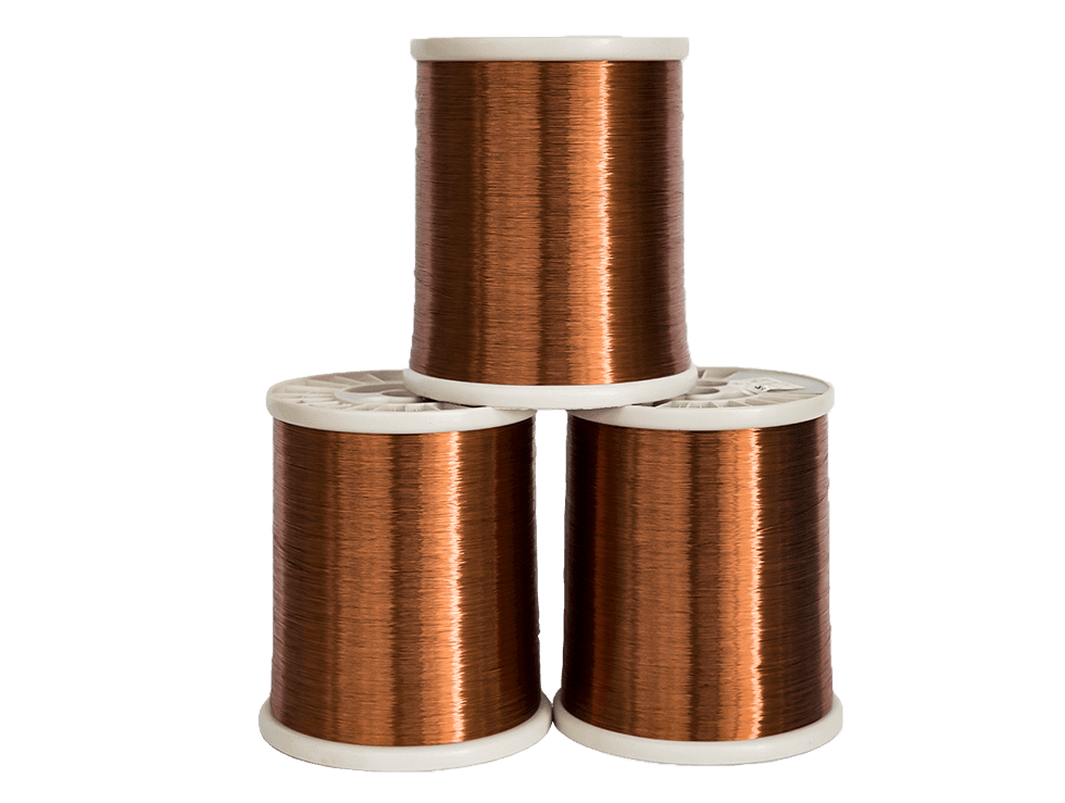
Polyurethane insulation is widely used in electronics manufacturing due to its unique chemical properties. It acts as an excellent dielectric barrier at room temperature but decomposes cleanly when exposed to the heat of a soldering iron (typically around 360°C to 400°C). This allows the wire to be soldered directly to terminals without prior mechanical or chemical stripping.
Direct solderability drastically reduces manufacturing cycle times and eliminates the risk of nicking the ultra-fine copper conductor during mechanical stripping. It is the standard choice for small transformers, inductors, relays, and small motors. Polyurethane has strict thermal limitations. It is typically rated for Class 155 (155°C) or Class 180 (180°C). Exposing polyurethane-insulated wire to continuous operating temperatures above its rating causes the polymer chains to break down, leading to rapid short circuits.
Applications generating significant heat require robust insulation chemistries. Polyesterimide (Class 200) and Polyamide-imide (Class 220-240) offer exceptional thermal stability. To maximize both thermal and mechanical resilience, manufacturers often produce dual-coated wires. A common configuration is a polyesterimide base coat for high dielectric strength, covered by a polyamide-imide topcoat for superior abrasion resistance and chemical defense.
These high-temperature enamels are mandatory for high-density transformers, automotive actuators, power tools, and industrial electric motors. The primary trade-off for this durability is the lack of direct solderability. Polyamide-imide does not melt away under a soldering iron. It requires mechanical stripping using high-speed fiberglass wheels or aggressive chemical stripping before the wire can be terminated. This adds complexity to the manufacturing process but guarantees survival in harsh environments.
Certain precision components, such as voice coils for speakers, vibration motors for smartphones, and coreless motors for medical tooling, eliminate the physical bobbin entirely to save space and weight. These freestanding coils rely on self-bonding enameled wire to hold their shape.
Self-bonding wire features a standard base insulation coated with an additional thermoplastic bonding layer. After the coil is wound, this outer layer is activated. Activation methods include baking the coil in an oven, passing a high current through the wire to generate internal heat, or applying a specific solvent during winding. Once the bonding layer cools or the solvent evaporates, the turns fuse together, creating a rigid, self-supporting coil.
The thickness of the enamel coating, referred to as the build, determines the wire's dielectric strength and its resistance to physical abrasion. Standards define three primary builds. You must match the insulation build to the expected electrical load and the physical realities of the manufacturing process. A thicker build increases the overall outer diameter of the wire, which reduces the fill factor of the coil.
Single Build (Grade 1): The thinnest coating. Used when space is the absolute priority and winding stresses are minimal. Offers the lowest dielectric breakdown voltage.
Heavy Build (Grade 2): The industry standard for most applications. Provides a balance of space efficiency, abrasion resistance, and dielectric strength.
Triple Build (Grade 3): The thickest coating. Specified for high-voltage applications or harsh winding environments where the wire is subjected to severe mechanical stress or crosses over itself frequently.
Insulation Type | Thermal Class | Direct Solderability | Primary Applications |
|---|---|---|---|
Polyurethane | 155°C - 180°C | Yes (at 360°C - 400°C) | Micro-transformers, relays, sensors |
Polyesterimide | 180°C - 200°C | No (Requires stripping) | Standard motors, solenoids, ballasts |
Polyamide-imide (Overcoat) | 200°C - 240°C | No (Requires stripping) | Automotive actuators, high-temp power supplies |
Polyurethane + Self-Bonding | 130°C - 155°C | Yes | Voice coils, coreless micro-motors |
Wire sizing relies on two primary systems: American Wire Gauge (AWG) and metric diameters (millimeters). In the AWG system, a higher number indicates a thinner wire. Fine enameled wire typically falls between AWG 30 (0.254 mm) and AWG 44 (0.050 mm). Ultra-fine wire extends beyond AWG 50 (0.025 mm).
Translating between AWG and metric measurements requires precision, especially in sub-0.2 mm ranges. A minor rounding error in conversion can lead to specifying a wire that physically will not fit into the designed bobbin space. Standard sizing charts often list nominal diameters. When dealing with precision micro-electronics, you must work with exact minimum and maximum tolerances for both the bare copper conductor and the overall outer diameter including insulation.
Quality control departments rely on dual-axis laser micrometers to continuously monitor the wire diameter as it exits the enameling oven. This ensures the wire remains perfectly round and within the specified tolerance band. If the wire becomes oval-shaped, it will twist during winding, causing unpredictable tension spikes and uneven coil layers.
Dimensional tolerance is non-negotiable in high-speed automated winding. Microscopic variations in wire diameter directly alter the fill factor of a coil. If the wire diameter runs consistently on the high side of the tolerance band, a coil designed to hold 1,000 turns may only fit 950 turns before overflowing the bobbin. This alters the inductance and resistance of the final component.
Inconsistent outer diameters cause severe issues with CNC winding machines. Winding tensioners rely on a consistent wire surface to maintain steady tension. If the wire diameter fluctuates, the tension spikes and drops. Tension spikes cause the soft copper to stretch, changing its resistance, or snap entirely, halting production. Specifying electrical component wire with tight dimensional tolerances ensures smooth feeding through ceramic eyelets and tensioning pulleys, maximizing production yield.
The performance of a coil is only as reliable as the wire used to wind it. A credible magnet wire manufacturer implements stringent quality control protocols to ensure batch-to-batch consistency. Traceability is equally critical. Manufacturers must track the source of the raw copper rod and the specific batches of insulation varnish used. If a field failure occurs, traceability allows engineers to isolate the affected batch and prevent widespread product recalls.
Essential testing protocols include:
Pinhole Testing: High-voltage continuity tests detect microscopic flaws or gaps in the enamel coating. Pinholes lead to turn-to-turn short circuits.
Elongation and Tensile Testing: Verifies the mechanical properties of the copper, ensuring the temper is consistent and will not stretch unpredictably during winding.
Dielectric Breakdown Testing: Applies increasing voltage to twisted pairs of wire until the insulation fails, verifying the thermal and electrical integrity of the enamel build.
Springback Testing: Measures the wire's tendency to uncoil after being wound, ensuring the temper is soft enough for tight bobbins.
Global compliance standards dictate the chemical composition and performance metrics of electrical wire. Manufacturers must provide documentation proving compliance with RoHS and REACH to ensure the wire contains no banned heavy metals or toxic compounds.
Performance testing is governed by regional standards. In North America, NEMA MW 1000 dictates the dimensional, electrical, and mechanical requirements for magnet wire. Internationally, IEC 60317 serves as the primary standard. You must verify that the wire meets the specific standard required by your target market, as testing methodologies for thermal endurance and abrasion resistance differ slightly between NEMA and IEC protocols.
Off-the-shelf wire is often insufficient for highly specialized applications. When standard specifications fail to meet design constraints, you must rely on custom capabilities. This includes specifying non-standard insulation builds or applying specific bonding layers tailored to unique solvent activation processes.
Custom spooling and packaging are also vital. The physical spool must integrate seamlessly with the specific de-reeling equipment used on the production floor. Spool sizes range from small PT-4 spools for ultra-fine wire to massive tapered reels for heavier gauges. The winding pattern on the spool itself dictates how smoothly the wire pays off into the CNC machine. A specialized manufacturer providing custom winding wire can adjust spool tension and winding patterns to prevent wire entanglement during high-speed automated payout.
Sourcing fine wire involves balancing commercial realities with technical requirements. Custom specifications often come with high Minimum Order Quantities (MOQs) because setting up drawing dies and enamel curing ovens for a unique run is time-intensive. Seek manufacturers capable of providing smaller prototyping runs before committing to full-scale production volumes. Understanding the lead times for custom copper alloys or specialized insulation colors is necessary to prevent supply chain bottlenecks during product launches.
Calculate the maximum allowable resistance based on the physical constraints of your bobbin to determine the exact wire gauge required.
Specify the thermal class by adding the maximum ambient temperature to the internal heat rise of the component under full load.
Match the insulation chemistry to your manufacturing process, selecting polyurethane for direct solderability or polyamide-imide for high-heat environments.
Audit your wire supplier's testing protocols for pinholes, elongation, and dimensional tolerances before approving a production batch.
Request prototype spools that match your production de-reeling equipment to verify tension control during high-speed automated winding.
A: Single build (Grade 1) has a thinner enamel coating, saving space in tight winding applications but offering lower dielectric strength. Heavy build (Grade 2) has a thicker coating, providing superior abrasion resistance and higher dielectric breakdown voltage, making it the standard for most industrial applications.
A: Fine copper stretches when the winding tension exceeds the wire's yield strength. This occurs due to improper tensioner settings on the CNC machine, inconsistent wire outer diameters causing tension spikes, or specifying a wire temper that is too soft for the applied mechanical load.
A: No. Polyurethane is typically rated for Class 155°C or 180°C and is designed to melt under soldering heat. In high-temperature motors, continuous heat will degrade the polyurethane, causing short circuits. Polyamide-imide or polyesterimide (Class 200°C+) must be used instead.
A: Self-bonding wire features an outer thermoplastic layer over the primary insulation. After winding the coil, this layer is activated by heat, electrical resistance, or chemical solvents. Once activated and cooled, it fuses the turns together, allowing the coil to hold its shape without a physical bobbin.
A: Specify OFC for ultra-fine wire applications (sub-0.05 mm) or applications requiring extreme mechanical flexing. OFC lacks microscopic oxygen inclusions, making it more ductile, less prone to breaking during high-speed drawing, and slightly more conductive than standard ETP copper.
A: No. While natural enamel colors vary by chemistry, manufacturers frequently add dyes for phase identification or visual inspection. Always rely on the technical data sheet for thermal class ratings rather than visual color.


