
Please Choose Your Language
- All
- Product Name
- Product Keyword
- Product Model
- Product Summary
- Product Description
- Multi Field Search

Views: 0 Author: Site Editor Publish Time: 2026-08-25 Origin: Site


High-efficiency motor design, miniaturization, and high-density electromagnetic applications are pushing standard winding materials to their physical and thermal limits. Complex coil geometries, tight bending radii, and high-speed automated winding processes introduce severe mechanical stress. Using rigid or improperly insulated wire leads to insulation micro-cracking, short circuits, reduced copper-to-space ratios (fill factors), and premature component failure. Specifying purpose-built flexible enameled wire mitigates mechanical degradation during manufacturing while maintaining strict dielectric and thermal performance standards. This guide provides a technical framework for evaluating and sourcing the correct flexible wire for demanding winding applications.
Mechanical Resilience: Flexible enameled wire utilizes specialized polymer films (e.g., modified polyurethane, polyimide) that withstand high elongation and tight-radius bending without compromising dielectric integrity.
Fill Factor Optimization: Balancing wire gauge, flexibility, and insulation thickness is critical for maximizing the copper-to-space ratio and managing electrical resistance in high-density motor and coil designs.
Thermal and Electrical Alignment: Selection must align with specific thermal classes (155°C to 240°C) and operating environments, balancing flexibility with high-temperature endurance.
Supplier Capabilities: Partnering with a qualified custom wire supplier is essential for securing non-standard gauges, proprietary insulation blends, custom jacketed overcoats, and rigorous batch-to-batch consistency.
High-speed CNC winding equipment exerts immense physical forces on conductive materials. As wire travels from the payoff spool to the stator or bobbin, it experiences severe axial tension. The wire must change direction sharply around stator teeth, guide pins, and tight corners. Standard enamel coatings lack the necessary elasticity to survive these rapid directional changes. Under high tension, rigid polymer insulation fractures or thins out along the outer edge of the bend.
When a needle winder forces wire into a narrow stator slot, the material undergoes simultaneous compression on the inner radius and extreme elongation on the outer radius. Friction against ceramic eyelets or steel winding guides further degrades the coating, stripping away the protective layer and exposing the bare metal. These microscopic fractures compromise the dielectric barrier. You end up with immediate electrical faults on the production line or latent failures that surface months later in the field.
Common failure points during automated winding include:
Tensioner Spikes: Sudden acceleration of the winding flyer causes tension spikes that stretch the copper beyond its yield point, cracking the enamel.
Guide Pin Abrasion: Wire dragging across worn tooling scrapes the outer polymer layer, reducing the dielectric strength.
Corner Shearing: Bending wire at 90-degree angles around square bobbins causes standard enamel to craze and flake off.
Slot Insertion Damage: Pushing wound coils into stator slots tears the insulation if the wire lacks a durable, low-friction overcoat.
Engineers face a strict physical trade-off when designing high-efficiency electromagnetic devices. Maximizing current-carrying capacity requires using thicker wire to lower electrical resistance. However, thicker wire is inherently stiffer and resists conforming to tight spaces. When stiff wire is forced into confined stator slots or wound around small bobbin cores, it fails to pack densely.
This poor packing reduces the overall copper-to-space ratio, commonly known as the fill factor. A low fill factor decreases motor efficiency and increases heat generation. Achieving a high fill factor requires insulation that can compress and stretch without losing its dielectric strength. Flexible wire enables orthocyclic winding, where each turn of wire sits perfectly in the groove created by the previous layer. This precise packing can push the fill factor above 85%, but it is physically impossible if the wire springs back or resists bending.
Winding Type | Typical Fill Factor | Wire Flexibility Requirement | Primary Application |
|---|---|---|---|
Random Winding | 35% - 45% | Low to Moderate | Standard AC Induction Motors |
Layer Winding | 50% - 60% | Moderate | Transformers, Solenoids |
Orthocyclic Winding | 75% - 85%+ | Extremely High | High-Efficiency Servos, Aerospace |
Micro-electronics, precision sensors, and miniature actuators demand extreme bend radii. In these applications, the physical space available for the coil is microscopic. Standard wire fails catastrophically under these conditions. The insulation cracks instantly when forced into sharp, acute angles. Losing dielectric strength in a micro-coil renders the entire sensor useless.
Superior elongation properties are mandatory for these applications. The insulation must stretch uniformly with the conductor, maintaining a continuous, pinhole-free barrier even when the wire is bent back upon itself. In medical implants or tiny aerospace actuators, wire gauges often drop below 40 AWG. At these microscopic diameters, the enamel layer is incredibly thin. Any lack of flexibility results in immediate short circuits during the winding process.
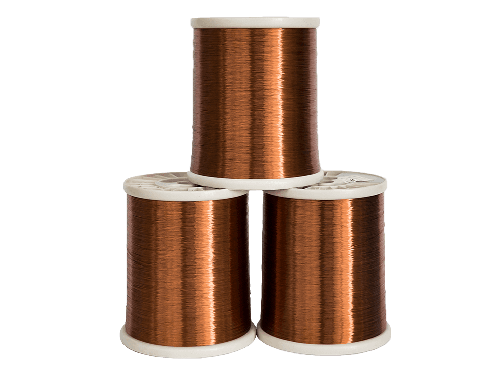
Polymer flexibility relates directly to its thermal resistance and chemical structure. Modified polyurethane offers excellent flexibility and solderability, making it ideal for lower-temperature applications where rapid termination is required. High-thermal-class films, such as polyimide or polyamide-imide, handle environments exceeding 200°C. These high-temperature polymers are naturally rigid.
Manufacturers must carefully formulate and apply these films in precise layers to maintain pliability without sacrificing thermal endurance. Custom jacketed overcoats provide an additional layer of mechanical protection. Applying a nylon overcoat over a base insulation yields superior abrasion resistance. This dual-layer approach protects the base dielectric film during aggressive slot insertions while keeping the overall wire flexible enough for tight routing.
Polymer Type | Thermal Class | Flexibility Rating | Abrasion Resistance |
|---|---|---|---|
Polyurethane (PU) | 130°C - 155°C | Excellent | Low |
Polyesterimide (PEI) | 180°C | Good | Moderate |
Polyamide-imide (PAI) | 200°C - 220°C | Moderate | High |
Polyimide (PI) | 240°C+ | Low (Requires modification) | Very High |
Selecting the right base metal is as critical as the insulation. enameled copper wire serves as the industry baseline for applications demanding maximum electrical conductivity. Copper delivers exceptional current-carrying capacity and superior tensile strength, allowing it to withstand high winding tension without stretching out of specification. The high modulus of elasticity in copper ensures it holds its shape once wound.
Enameled aluminum wire offers a solution for weight-sensitive applications, such as aerospace components or lightweight automotive coils. Aluminum possesses lower yield strength and different bendability characteristics compared to copper. It is highly susceptible to conductor fatigue if bent repeatedly. You must pair aluminum conductors with highly durable, specialized polymer films to prevent the insulation from shearing off when the softer metal deforms under winding pressure.
The cross-sectional area of the conductor dictates its absolute bend radius limits. Thicker wires naturally resist bending and require more force to shape. Manufacturers achieve flexibility in lower gauges (thicker wires) through specialized, highly controlled annealing processes. Annealing alters the grain structure of the metal, softening the conductor and increasing its ductility.
Extremely thick windings, known as heavy builds, require engineered insulation layers to maintain flexibility. These heavy builds safely raise the copper-to-space ratio by providing a thicker dielectric barrier that resists thinning at the corners. If the annealing process is inconsistent, the wire will exhibit hard spots. These hard spots refuse to bend uniformly, causing the wire to bulge out of the winding area and destroying the fill factor.
Electric vehicle traction motors, industrial servomotors, and aerospace actuators operate under extreme electrical and mechanical stress. motor winding wire used in these applications must resist severe abrasion during automated slot insertion. The insulation must also withstand high-frequency inverter spikes that cause partial discharge and rapid thermal cycling.
You need high-strength enamel that stretches uniformly without thinning at the apex of a bend. Utilizing high-grade flexible magnet wire prevents the formation of micro-cracks that eventually lead to catastrophic phase-to-phase shorts in high-voltage environments. In EV motors, hairpin winding techniques bend thick rectangular wire into tight U-shapes. The enamel on these rectangular wires must possess extraordinary adhesion and flexibility to survive the forming process without exposing the copper.
Relays, transformers, medical devices, and weak current technology operate on highly sensitive signals. coil winding wire for these devices requires absolute dimensional consistency and pinhole-free insulation. Any variance in insulation thickness alters the coil's inductance and capacitance, throwing the sensor out of calibration.
Self-bonding or self-adhesive variants are critical in this sector. These wires feature a specialized outer layer that bonds the coil together when exposed to specific heat or solvent triggers. This eliminates the need for secondary varnish dipping. Varnish dipping damages delicate micro-coils, alters tight dimensional tolerances, and introduces chemical contaminants to sensitive electronic assemblies. Self-bonding wire allows for rapid, clean manufacturing of freestanding coils.
Industrial environments expose electromagnetic coils to moisture, harsh chemicals, refrigerants, and aggressive transformer oils. The flexible coating must not degrade, soften, or swell over the product lifecycle. Swelling increases the physical size of the wire, forcing it out of the slot or causing mechanical stress on the surrounding components.
Specialized polymer blends, such as epoxy-modified resins or advanced polyamide-imides, ensure long-term stability. When winding motors for submersible pumps or hermetic compressors, the wire must endure constant exposure to pressurized fluids. If the enamel lacks chemical resistance, it will blister. Once the enamel blisters, the mechanical friction of the motor's vibration will rub the insulation away, causing a dead short to ground.
Specify exact operational and mechanical parameters before sourcing enameled winding wire. Vague specifications lead to component failure. Build a rigorous technical checklist for your engineering team to ensure the material matches the physical realities of your production floor.
Required dielectric strength to handle peak operating voltage and transient spikes.
Thermal class rating matching the absolute peak operating temperatures of the device.
Maximum acceptable elongation percentage required for the tightest bend radius in the coil geometry.
Target fill factor optimized for the specific stator slot or bobbin dimensions.
Maximum allowable electrical resistance per meter to ensure current-carrying requirements are met.
Abrasion resistance metrics required to survive the specific automated winding equipment used on the production floor.
Insulation flaking, poor adhesion, or concentricity variations lead directly to turn-to-turn shorts and failed quality control checks. Mitigate these risks by mandating strict adherence to international manufacturing standards, specifically NEMA MW 1000 or IEC 60317. Do not accept wire based on visual inspection alone.
Require continuous in-line pinhole testing data and concentricity reports from the manufacturer for every batch delivered. This ensures the insulation thickness remains perfectly uniform across the entire spool. Implement incoming quality control checks on your floor. Perform a mandrel bend test on every new spool. Wrap the wire around a mandrel three times its diameter and inspect the outer edge under magnification for any signs of crazing or cracking.
Evaluate the operational efficiency and production yield of utilizing premium, highly flexible custom wire. High-grade insulation drastically reduces manufacturing scrap rates by surviving aggressive winding speeds without fracturing. It prevents weak current signal loss in sensitive electronics, ensuring higher end-product reliability.
Upfront investment in superior elongation properties and custom overcoats directly lowers field warranty claims and replacement rates compared to utilizing off-the-shelf standard wire that cracks under tension. When a motor fails in the field due to a shorted winding, the cost of replacement, labor, and brand damage far exceeds the initial savings of buying cheaper, rigid wire. Prioritize mechanical survivability during the winding phase to guarantee long-term operational success.
A reliable custom wire supplier must possess rigorous, non-negotiable testing capabilities in-house. Look for documented elongation testing to verify the wire's ductility. Demand dielectric breakdown testing data to confirm insulation integrity under high voltage. Require thermal shock resistance verification to ensure the polymer does not crack when exposed to rapid temperature fluctuations.
Suppliers must utilize laser micrometers for continuous dimensional monitoring during the enameling process. Ask for their tangent delta testing results. Tangent delta testing verifies that the enamel is fully cured. Under-cured enamel is soft and scrapes off easily during winding. Over-cured enamel is brittle and shatters when bent. The supplier must prove they maintain the exact curing window required for maximum flexibility.
Evaluate the supplier's ability to engineer custom insulation builds tailored to your specific mechanical constraints. You may require specific build thicknesses, such as Grade 1, 2, or 3, to balance flexibility and dielectric strength. Check their capabilities in applying custom jacketed overcoats and drawing bespoke alloy conductors.
Rapid prototyping is essential for iterative motor design. The supplier must be capable of producing short-run sample spools quickly. This allows your engineering team to validate the wire's performance on actual winding equipment before committing to mass production. If a supplier forces massive minimum order quantities for prototype runs, they will bottleneck your development cycle.
Assess the vendor's capacity to maintain tight dimensional tolerances across high-volume production runs. Batch-to-batch variance in insulation thickness or copper temper ruins automated winding calibration, leading to massive production downtime. If one batch of wire is slightly stiffer than the last, your CNC winder will throw tension errors and snap the wire.
Ensure the supplier has robust raw material sourcing protocols for both the base metals and the polymer resins to prevent production delays. Audit their quality management systems, looking for ISO 9001 and IATF 16949 certifications if supplying the automotive sector. Review their spooling and packaging methods. Poorly spooled wire tangles during high-speed payoff, causing instant machine jams and broken conductors.
Calculate your required fill factor based on exact slot dimensions and current requirements to determine the maximum allowable wire gauge.
Review the automated winding tension limits and guide friction points on your production floor to establish baseline abrasion resistance needs.
Request detailed technical data sheets and tangent delta curing reports from a verified custom wire supplier.
Order sample spools for rigorous prototype testing, including mandrel bend tests and destructive analysis on your specific winding equipment.
A: Flexible magnet wire utilizes specialized annealing processes and advanced polymer formulations to provide superior elongation capabilities. Standard wire features rigid enamel that often cracks under tight bending radii. Flexible variants stretch and conform to sharp corners, preventing insulation failure and maintaining dielectric strength during high-speed winding.
A: Wire thickness and flexibility share an inverse relationship. Thicker gauges lower electrical resistance and increase current-carrying capacity but are inherently stiffer. Engineers use specialized annealing and heavy-build flexible insulations to bend thicker wires safely into confined stator slots without fracturing the coating.
A: Modified polyurethanes offer exceptional flexibility and solderability for lower thermal classes. For higher temperatures, specific polyester blends and polyamide-imide formulations maintain pliability. Custom jacketed nylon overcoats are frequently applied over base insulations to provide extreme abrasion resistance and flexibility during tight slot insertions.
A: Yes, provided the wire features a high-strength, flexible enamel coating. The winding equipment must also be precisely calibrated to the wire's specific tension and elongation limits. Proper setup prevents the insulation from thinning out or stripping as it passes rapidly through guides and around sharp bobbin pins.
A: Self-adhesive enameled wire features a specialized outer layer that bonds the coil together when exposed to heat or solvents. It is essential in weak current technology and precision coil winding applications. It eliminates the need for secondary varnish dipping, which can damage delicate micro-coils or alter tight dimensional tolerances.
A: Flexible enameled wire typically spans thermal classes from 155°C to 240°C. Lower thermal classes use highly flexible polyurethanes. Higher thermal classes require stiffer polyimide or polyamide-imide base insulations. Manufacturers carefully modify these high-temperature polymers to retain enough flexibility for complex winding without sacrificing thermal endurance.
A: Look for a supplier with strict ISO certifications and documented adherence to NEMA or IEC standards. They must possess in-house testing capabilities for elongation, dielectric strength, and thermal shock. Ensure they can produce custom insulation builds, specific gauges, and rapid prototypes to support your iterative design process.


