
Please Choose Your Language
- All
- Product Name
- Product Keyword
- Product Model
- Product Summary
- Product Description
- Multi Field Search

Views: 0 Author: Site Editor Publish Time: 2026-08-11 Origin: Site


In high-density motors, transformers, and precision inductors, off-the-shelf magnet wire often falls short of specific thermal, mechanical, or spatial constraints. This forces engineers to seek custom engineered solutions. Misalignment between engineering design requirements and manufacturing realities leads to severe issues on the production floor. You might experience insulation micro-cracking during high-speed winding, premature dielectric breakdown in the field, or unacceptable yield rates. Bridging the gap from prototype to scalable production requires a rigorous specification process. Standard wire catalogs cannot account for the unique stresses of proprietary winding equipment or extreme operating environments. This guide details the exact technical parameters, material trade-offs, and quality validation frameworks required to successfully partner with a custom manufacturer. You will learn how to align your application demands with manufacturing capabilities to ensure reliable, high-yield coil production.
Material and Profile Optimization: Selecting between enameled copper wire and enameled aluminum wire—and determining round vs. rectangular profiles—dictates both the spatial efficiency (fill factor) and thermal management of the final coil.
Insulation Specification is Critical: Thermal class ratings (e.g., Class 155 to 240) and enamel build thickness must precisely match the operating environment and the mechanical stress of the automated winding process.
Manufacturing Process Awareness: Understanding the supplier's cleaning, coating, curing, and precision take-up processes is essential for auditing quality and preventing pre-stressed wire deliveries.
Supplier Validation: A qualified winding wire supplier must demonstrate rigorous in-line testing (pinhole, dielectric, elongation), raw material traceability, and strict tension control to mitigate implementation risks.
Establishing the baseline electrical, thermal, and mechanical demands of your end application is mandatory before contacting a manufacturer. You cannot engineer a custom solution without defining the exact failure boundaries of your current design. Documenting these parameters ensures the resulting custom magnet wire performs reliably under continuous stress on the factory floor and in the field.
You must document continuous operating temperatures and anticipated peak temperature spikes. Voltage ratings and required dielectric strength dictate the necessary insulation thickness. High-voltage applications demand thicker enamel builds to prevent arc faults between adjacent turns. Consider the operating environment carefully. Will the coil sit in a sealed, oil-filled transformer, or will it face ambient humidity and corrosive gases? These factors directly influence the chemical resistance required from the enamel coating. We often see failures when engineers specify a standard thermal class without accounting for localized hot spots within the stator slots. You need to map the thermal gradient across the entire winding assembly to ensure the base resin can handle the absolute peak temperatures without degrading.
Evaluate the tension control requirements of your manufacturing facility's take-up process. High-speed automated winding machines exert immense mechanical stress on the wire. The wire must possess specific flexibility. The enamel adhesion must be strong enough to prevent flaking or micro-cracking as the wire bends sharply around bobbins or stator teeth. If your winding process involves aggressive needle winding, you must specify higher abrasion resistance for the outer coating. Document the exact bending radii your tooling imposes on the wire. A tight bending radius requires a highly flexible enamel formulation to prevent the outer radius of the insulation from splitting open during the winding cycle.
Calculate the required slot fill percentage. This calculation determines if standard round wire is sufficient or if custom shaped wire is necessary. High-efficiency motors often require maximum conductor density within confined stator slots. If your design demands a slot fill above 75%, standard round profiles will likely fail to meet the spatial constraints. You must evaluate the physical volume available and match it against the required cross-sectional area of the conductor. Wasted space in a stator slot translates directly to lost motor efficiency and increased operating temperatures. Precision engineering of the wire profile is the only way to maximize the magnetic field generation within a fixed physical footprint.
Evaluating the core conductor material requires balancing conductivity, weight, and termination requirements. The choice between copper and aluminum fundamentally alters the design of the coil, the winding process, and the final product weight. You must weigh the electrical benefits against the mechanical realities of your production line.
Copper remains the industry standard for high-performance electromagnetic applications. It provides unmatched reliability in dense, high-power environments. You should specify enameled copper wire for high-efficiency motors, compact transformers, and applications where spatial constraints override weight concerns.
Superior electrical conductivity allows for a smaller cross-section to carry the same current, reducing the overall footprint of the coil.
Lower overall volume makes it ideal for compact designs where space is at an absolute premium.
High tensile strength withstands aggressive automated winding speeds without stretching or necking down.
Straightforward soldering and termination processes reduce manufacturing complexity and cycle times.
Heavier overall weight limits its use in weight-sensitive aerospace or mobile applications.
Aluminum offers distinct advantages for specific engineering challenges, primarily regarding mass reduction. Engineers typically select enameled aluminum wire for aerospace components, automotive coils, and large-scale transformers where weight reduction is a strict design mandate.
Significant weight reduction, often up to 50% lighter than a copper equivalent, which is critical for EV motors and aerospace actuators.
Highly stable raw material costs provide predictable manufacturing expenses over long production runs.
Lower conductivity requires a larger cross-sectional area to match copper's current capacity, requiring larger stator slots.
Lower tensile strength demands highly precise tension control during the winding process to prevent the wire from stretching and altering its resistance.
Complex termination requires specialized joining processes like ultrasonic welding or specialized crimps to pierce the tough aluminum oxide layer.
Property | Copper Conductor | Aluminum Conductor |
|---|---|---|
Density (g/cm³) | 8.89 | 2.70 |
Electrical Conductivity (% IACS) | 100% | 61% |
Tensile Strength (MPa) | 200 - 250 | 70 - 90 |
Termination Method | Standard Soldering / Brazing | Ultrasonic Welding / Specialized Crimping |
Primary Application Focus | Maximum Efficiency / Compact Size | Weight Reduction / Cost Stability |
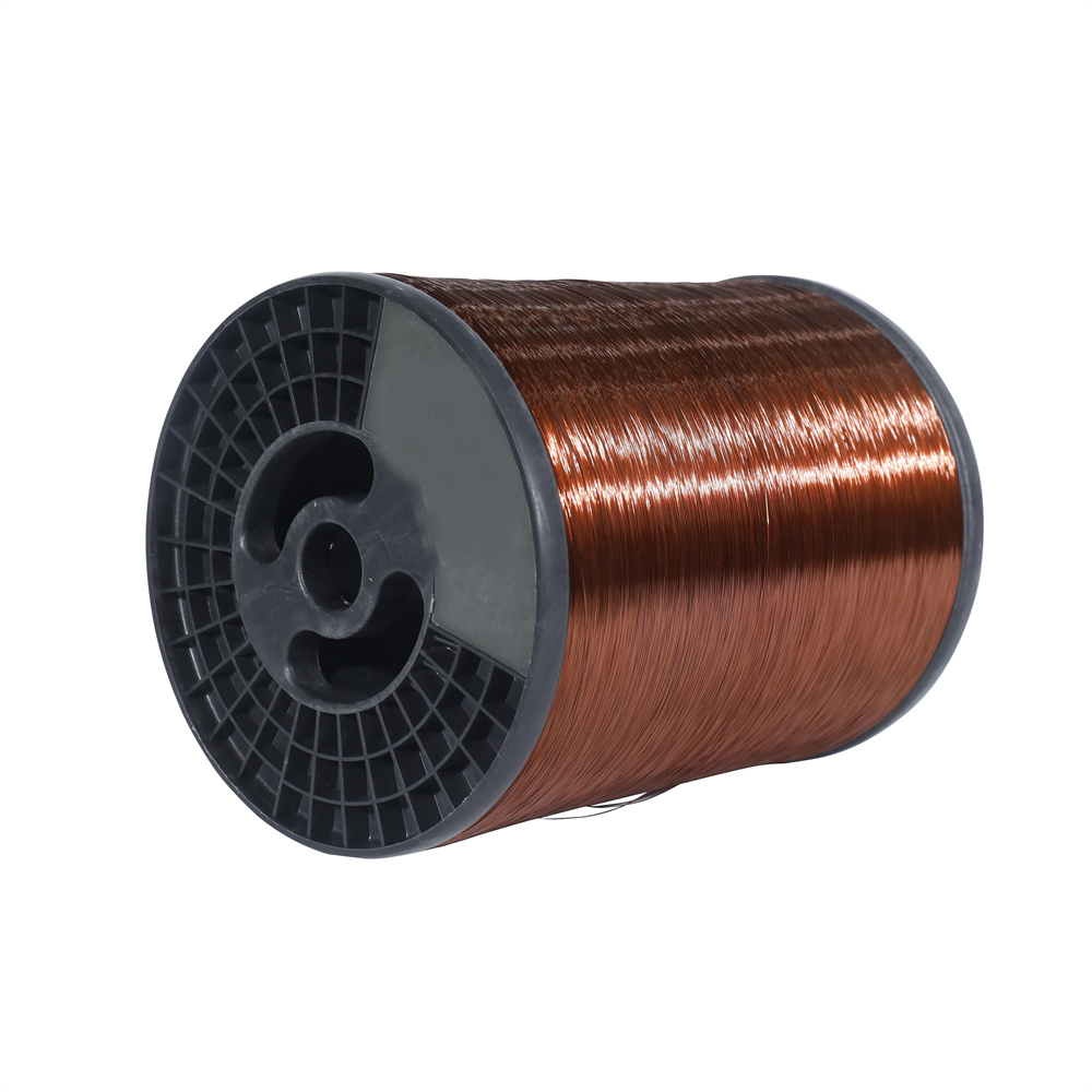
Wire geometry directly impacts electromagnetic performance, thermal dissipation, and manufacturing complexity. You must evaluate how the cross-sectional shape aligns with your slot design. The physical profile of the wire dictates how tightly you can pack the conductors and how effectively you can extract heat from the core of the winding.
Round wire is highly cost-effective and easier to manufacture. Standard tooling is readily available across the industry. It remains suitable for applications with flexible spatial constraints. When slot fill factors hover around 60% to 70%, round wire provides a reliable, easy-to-wind solution. The symmetrical shape ensures uniform enamel distribution during the coating process, reducing the risk of thin spots. Winding machines handle round wire easily, as it can twist slightly during the take-up process without causing dimensional interference in the coil.
Shaped wire solves complex spatial and thermal challenges in high-density applications. It requires specialized OEM enameled wire manufacturing capabilities to produce accurately without damaging the insulation on the corners.
Maximizes slot fill factor, achieving up to 90% density compared to round wire limits.
Improves heat dissipation significantly due to larger surface area contact between adjacent turns, eliminating insulating air pockets.
Reduces skin effect in high-frequency applications when specific aspect ratios are utilized, pushing current to the wider surface area.
Demands precise corner-radius specifications to prevent enamel thinning on sharp edges, which would otherwise create weak points for dielectric breakdown.
Requires custom drawing dies and specialized handling equipment on the winding floor to prevent the wire from twisting out of alignment.
Matching the chemical and thermal properties of the enamel to the application prevents premature field failures. The insulation must survive both the manufacturing process and the operational lifespan of the device. You cannot afford to under-specify the enamel build, nor should you over-specify it and waste valuable slot space.
You must specify NEMA, IEC, or JIS standards for thermal endurance. Different base resins offer varying temperature ceilings. Polyurethane is common for Class 155 and 180 applications, offering excellent solderability without prior stripping. This speeds up production times significantly. Polyamide-imide or Polyimide resins are mandatory for Class 200, 220, and 240 applications. These high-temperature resins resist severe thermal overloads but require mechanical or chemical stripping before termination. Using a Class 155 wire in a Class 200 environment guarantees a catastrophic short circuit as the resin melts and flows away from the conductor.
Thermal Class | Base Resin Material | Solderability | Typical Application Environment |
|---|---|---|---|
Class 155 (F) | Polyurethane | Direct Solderable (390°C) | Relays, small transformers, consumer electronics. |
Class 180 (H) | Polyester-imide | Requires Stripping | Standard industrial motors, generators, power tools. |
Class 200 (N) | Polyamide-imide | Requires Stripping | Heavy-duty traction motors, high-temp transformers. |
Class 220/240 | Polyimide | Requires Stripping | Aerospace actuators, extreme environment sensors. |
Selecting the correct build thickness involves a strict engineering trade-off. Thicker builds increase dielectric protection and mechanical durability. However, they reduce the overall fill factor and impede heat transfer efficiency. Single build (Grade 1) offers maximum space efficiency for low-voltage applications. Heavy build (Grade 2) is the industry standard for most motors and transformers, providing a reliable balance of protection and size. Triple build (Grade 3) is reserved for high-voltage applications or environments where the wire faces severe mechanical abrasion during the winding process.
Beyond standard insulation, specialty topcoats solve specific manufacturing challenges. Bondable overcoats allow for the creation of self-supporting coils without plastic bobbins. These overcoats activate via heat or solvent application after winding, fusing the turns together into a rigid mass. Self-lubricating coatings reduce surface friction. This prevents the wire from snapping or scraping as it feeds through the machine nozzles during high-speed, high-tension precision winding. Specifying a self-lubricating topcoat can drastically reduce scrap rates on automated winding lines.
Engineers must understand how custom enameled wire is manufactured. This process transparency allows you to accurately audit a supplier's capabilities from raw material intake to final delivery. Knowing the failure points in the manufacturing process helps you write better specifications.
The foundation of quality insulation is a pristine conductor surface. Ensure the supplier utilizes high-purity raw materials. Rigorous cleaning processes must remove all drawing lubricants, oxidation, and surface contaminants. Any microscopic debris left on the bare wire will cause poor enamel adhesion, leading to blistering or flaking during the winding process. The wire must pass through an annealing furnace to soften the metal, relieving the work-hardening stresses introduced during the drawing process. Improper annealing leaves the wire too stiff, causing it to spring back out of the stator slots.
Manufacturers apply resin in precise, concentric layers to achieve the specified build thickness. This is typically done via extrusion dies or felt wiping methods. Extrusion dies provide superior concentricity for shaped wires and heavy builds. The application must be uniform. Irregularities in the coating process create weak points in the dielectric barrier, which inevitably lead to short circuits in the field. The wire passes through the coating applicator multiple times, building up the insulation in microscopic layers to ensure a pinhole-free barrier.
Thermal processing cross-links the polymer resin into a durable film. Suppliers must demonstrate exceptionally tight temperature controls within their curing ovens. The ovens feature multiple temperature zones to evaporate the solvents slowly before cross-linking the base resin. Under-curing results in poor chemical resistance and a soft coating that easily scrapes off on your winding machine guides. Over-curing creates a brittle enamel layer that will crack instantly when the wire is bent around a tight radius.
Continuous winding at the manufacturer's facility must utilize perfect tension control. The take-up process determines how the wire behaves on your production floor. Poor spooling pre-stresses the wire. This leads to unwanted elongation, altered resistance values, or micro-cracking before the spool is even opened. Proper traverse winding ensures the wire pays off smoothly without tangling or snagging as it feeds into your high-speed winding equipment.
Understanding the commercial realities of custom production helps streamline the procurement process. Custom engineering requires specific workflows to validate designs before mass production begins. Partnering with a dedicated custom wire service ensures these workflows are managed efficiently, preventing costly delays during the prototyping phase.
Discuss how suppliers handle small-batch runs for prototype validation. You need a small quantity to test winding feasibility and electrical performance. However, custom runs require significant machine setup time. Understand the supplier's Minimum Order Quantities (MOQs) for full production. A reliable partner will offer a clear transition path from engineering samples to high-volume manufacturing, allowing you to validate the mechanical behavior of the wire on your specific tooling before committing to a massive production run.
Assess the upfront requirements associated with custom drawing dies. If your design requires a non-standard rectangular or square profile, the manufacturer must cut custom diamond or carbide dies. This introduces lead time delays. Factor these tooling schedules into your project timeline to avoid late-stage production bottlenecks. You must also account for the time required to manufacture custom extrusion dies for the enamel application, ensuring the corner radii of the insulation perfectly match the bare conductor.
A rigorous framework for auditing a potential manufacturing partner prevents catastrophic failures downstream. You must verify their quality control infrastructure. A qualified winding wire supplier will provide transparent access to their testing data and allow you to audit their production floor.
Verify the supplier audits the purity of incoming bare copper or aluminum rods. They must also test the chemical consistency and viscosity of the enamel resins before production begins. During production, the supplier must utilize continuous laser diameter measurement to ensure the wire stays within strict dimensional tolerances. High-voltage continuity testing must run in-line during the extrusion process to detect and log any pinhole faults immediately. If the in-line spark tester detects a fault, the system must automatically flag that section of the spool for removal.
Request comprehensive documentation on standard batch tests. You cannot rely on visual inspections; you need hard data proving the wire meets the specification.
Pinhole Fault Testing: Measures the number of insulation breaks per 100 feet of wire using a saltwater bath or high-voltage dry sponge.
Dielectric Breakdown Voltage: Ensures the insulation meets specified voltage ratings before catastrophic failure occurs between twisted pairs.
Thermal Shock Resistance: Verifies the enamel won't crack under rapid temperature changes, simulating aggressive operational cycling.
Elongation Testing: Confirms the wire can stretch slightly during winding without breaking or compromising the insulation adhesion.
Spring-Back Testing: Measures the wire's tendency to uncoil, ensuring it holds its shape in the stator slot without requiring excessive lacing.
Solvent Resistance Testing: Confirms the enamel will not degrade when exposed to varnishes, potting compounds, or transformer oils.
Ensure strict compliance with relevant industry standards. Look for UL recognized insulation systems. Verify RoHS and REACH compliance for environmental safety. If you are manufacturing automotive components, the supplier must hold ISO 9001 and IATF 16949 certifications. Full lot traceability ensures that if a failure occurs, you can track the exact raw material batch, production date, and machine operator. This traceability is non-negotiable for aerospace, medical, and automotive applications.
Securing high-quality wire is only half the battle. Preventing failure after the wire is delivered to your facility requires strict handling and processing protocols. Many perceived wire defects are actually caused by improper handling on the customer's production floor.
Enamel coatings can absorb moisture or degrade under intense UV light over time. Specify strict packaging requirements. Request vacuum-sealed spools and the use of specific desiccants for long transit times. Implement climate-controlled storage protocols on your factory floor. Keep spools in their original packaging until immediately before use to prevent dust accumulation and moisture ingress. Dust particles settling on the wire will act as abrasives as the wire feeds through the winding machine nozzles.
Calibrate your lathes and winding machines specifically for the new custom batch. Thicker gauges require different tension settings than standard equivalents. Custom rectangular profiles demand specialized guide rollers to prevent the wire from twisting. Improper straightening tools can easily scrape the enamel off the corners of shaped wire. Inspect all machine contact points for wear, grooving, or sharp edges. A single worn ceramic eyelet can strip the insulation off an entire spool of wire before the operator notices the defect.
Prevent micro-cracking during the take-up process by calibrating winding machine tensioners. The tension must match the specific yield strength of the custom batch. This is especially critical for aluminum wire, which stretches and breaks under lower tension than copper. Conduct visual and electrical inspections of the first wound coils from a new batch to verify that the winding process is not compromising the dielectric barrier. Implement surge testing on the wound coils before they move to the varnishing or potting stages to catch any turn-to-turn shorts early in the assembly process.
Audit your current winding machine tension capabilities and guide roller geometries before specifying conductor yield strength.
Draft a comprehensive specification sheet detailing exact corner radii, thermal class, and enamel build thickness for your required profile.
Request in-line spark testing logs and raw material purity certificates from your shortlisted manufacturers.
Order a small prototype spool to validate automated winding speeds and termination processes before committing to full production volumes.
A: The thermal classification indicates the maximum continuous operating temperature the insulation can withstand. Class 155 typically uses polyurethane and is solderable without stripping. Class 200 uses polyamide-imide or polyimide, offering superior heat resistance but requiring mechanical or chemical stripping before soldering.
A: Rectangular wire maximizes the slot fill factor, allowing up to 90% conductor density compared to roughly 70% for round wire. This increases motor efficiency and torque while improving heat dissipation due to larger surface contact between adjacent turns.
A: Aluminum has lower tensile strength than copper. Winding machines must be carefully calibrated with lower tension settings to prevent stretching, necking, or breaking the wire. Additionally, joining aluminum requires specialized techniques like ultrasonic welding rather than standard soldering.
A: Flaking usually results from poor enamel adhesion during manufacturing, often due to inadequate bare wire cleaning. It can also occur if the wire is over-cured, making it brittle, or if the winding machine applies excessive tension and sharp bending radii.
A: A bondable overcoat is an additional outer layer of resin applied over the primary insulation. After winding, it is activated by heat or a solvent, causing the wire turns to fuse together. This creates a rigid, self-supporting coil without needing a plastic bobbin.
A: Suppliers use continuous in-line high-voltage continuity testing. The wire passes through a high-voltage electrode during production. Any break or thin spot in the enamel allows current to arc, which the system instantly detects and logs as a pinhole fault.


